Nmea 2000 Power Cable Wiring Diagram
Lowrance Help Topics Networking Diagrams Wiring Diagrams
Wiring Nmea 2000 Power To Ignition Switch The Hull Truth Boating And Fishing Forum

Boat Project Com Nmea2000 Primer
Nmea 2000 Power Problem Part 2 Panbo

Maretron Knowledge Base Questions

How Do I Connect A Maretron Field Makable Connector Or Field Attachable To An Nmea2000 Cable Print View
What s in the kit.
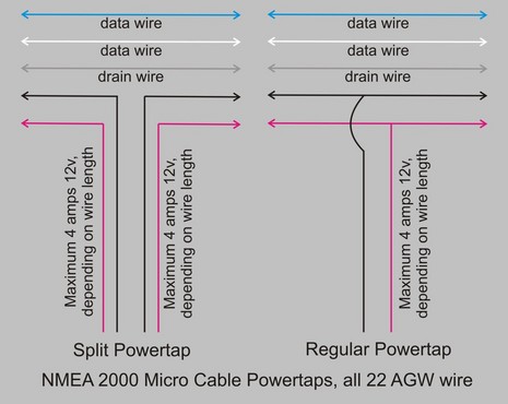
Nmea 2000 power cable wiring diagram. The nmea 2000 cable system includes five wires within a single waterproof cable. Starter kit part number. The 5 way connector forms the start of your seatalk ng backbone and your seatalk ng product is connected via a spur cable. A wiring diagram is a simplified conventional pictorial depiction of an electrical circuit.
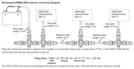
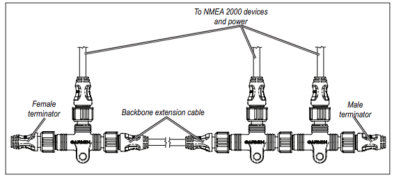
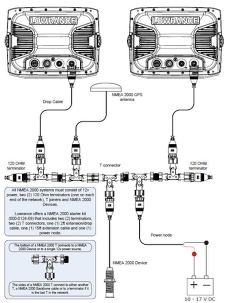
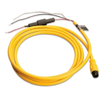
If you do not have an auxiliary power switch or if connecting to the auxiliary power switch causes electrical interference connect the nmea 2000 power cable directly to the battery and install an in line switch. The maximum length for a single drop cable is 20 feet. The seatalk ng starter kit is the perfect way to get started with your seatalk ng compatible raymarine product. If you require a longer cable run to connect an item such as a transducer or sea surface temperature sensor use a t junction to either at the end or the middle of the run to tie in 12 volt power.
Seatalk ng 5 way connector. Assortment of nmea wiring diagram. Augmenting the power helps prevent an excessive drop in voltage. A wiring diagram is a simplified conventional photographic depiction of an electric circuit.
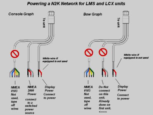
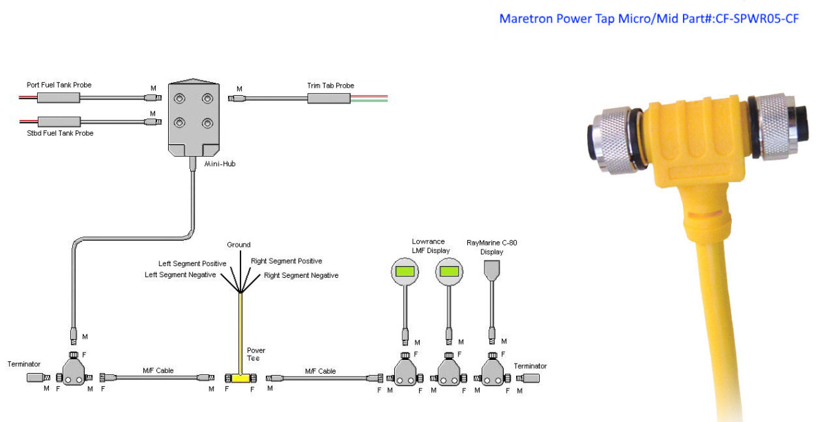
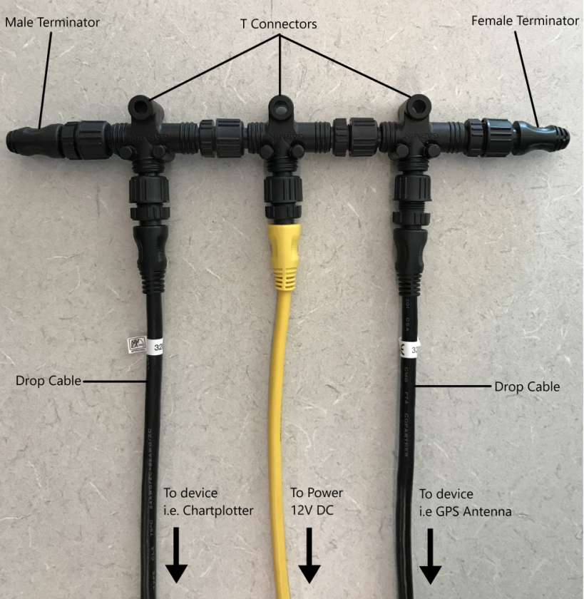
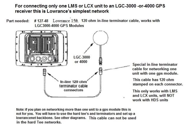
It reveals the parts of the circuit as streamlined forms and also the power and signal links between the gadgets. In this example a t connector is included with a garmin gfs 10 fuel sensor. In this case you would power your nmea network by connecting one of your lms or lcx unit power cables marked nmea power to a switched power source. In the sample box diagram a complete nmea 2000 network is shown and the parts included with the sensor are shaded.
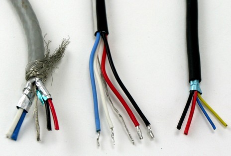
Nmea 2000 signals can be hampered by resistance which increases with cable length so keep the length for a single drop cable to less than 20 feet. If you require a longer cable run use a t junction in the middle of the run to tie in 12 volt dc power. Collection of nmea 2000 wiring diagram. Two signal wires power and ground wires and a drain wire.
Use a nmea 2000 power cable to connect your nmea 2000 backbone to the auxiliary power switch on your boat. A nmea 2000 power cable terminators an additional drop backbone cable and additional t connectors are not included with a gfs 10 fuel sensor. Nmea 2000 signals can be hampered by resistance which causes a reduction in voltage. The drain wire shields the signal power.
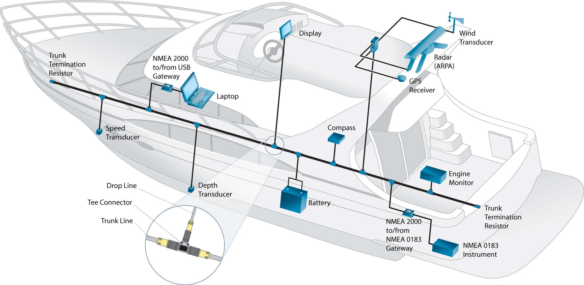
Maretron nmea 2000 cables connectors about nmea 2000 cables and connectors the nmea 2000 standard goes beyond defining message content and includes requirements for the cabling used to interconnect electronic components referred to as the physical interface. The following catalog pages contain the nmea 2000 approved network interconnect. Seatalk ng backbone terminator x2.
Diagram Nmea 2000 Network Wiring Diagrams Full Version Hd Quality Wiring Diagrams Ncp1011schematic5115 Fisiobenesseresegrate It
Adventures In Nmea 2000 Wiring Part I Panbo
Actisense Nmea 2000 Cables Connectors Passagemaker

Simrad Help Support How To Design And Build An Nmea 2000 Network
Nmea 2000 Building An Nmea 2000 Network Salt Water Sportsman

Nmea2000 Cabling Kit Digital Yacht
Garmin Nmea 2000 Wiring Diagram Diagram Base Website Wiring Diagram Venndiagramexcel Smartprojects It
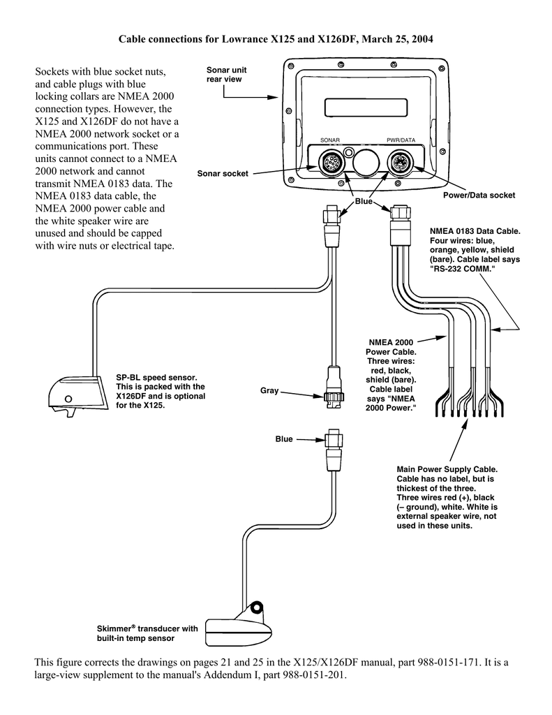
X125 And X126 Df Cable Connection Diagram Manualzz

Sk 2928 Garmin Power Wiring Diagram Schematic Wiring

Boat Project Com A Tutorial On Making A Basic Nmea 0183 Connection Between A Chartplotter And Vhf Radio
Tips Installing An Nmea 2000 Backbone On A Boat Youtube
Nmea 2000 Multiple Backbones T Questions The Hull Truth Boating And Fishing Forum

Echomap Uhd Nmea 2000 Considerations

Vhf 115 215 Ais Series Nmea 2000 Device Connections

Nmea 2000 Can Marine Interface Description Nmea 2000 Pin Out And Signal Names An Implementation Of The Controller Area Network In A Marine Environment

Gg 9388 Hds 8 Wiring Diagram Download Diagram

Connecting Our New Aisnode Receiver To A Garmin Network Digital Yacht News
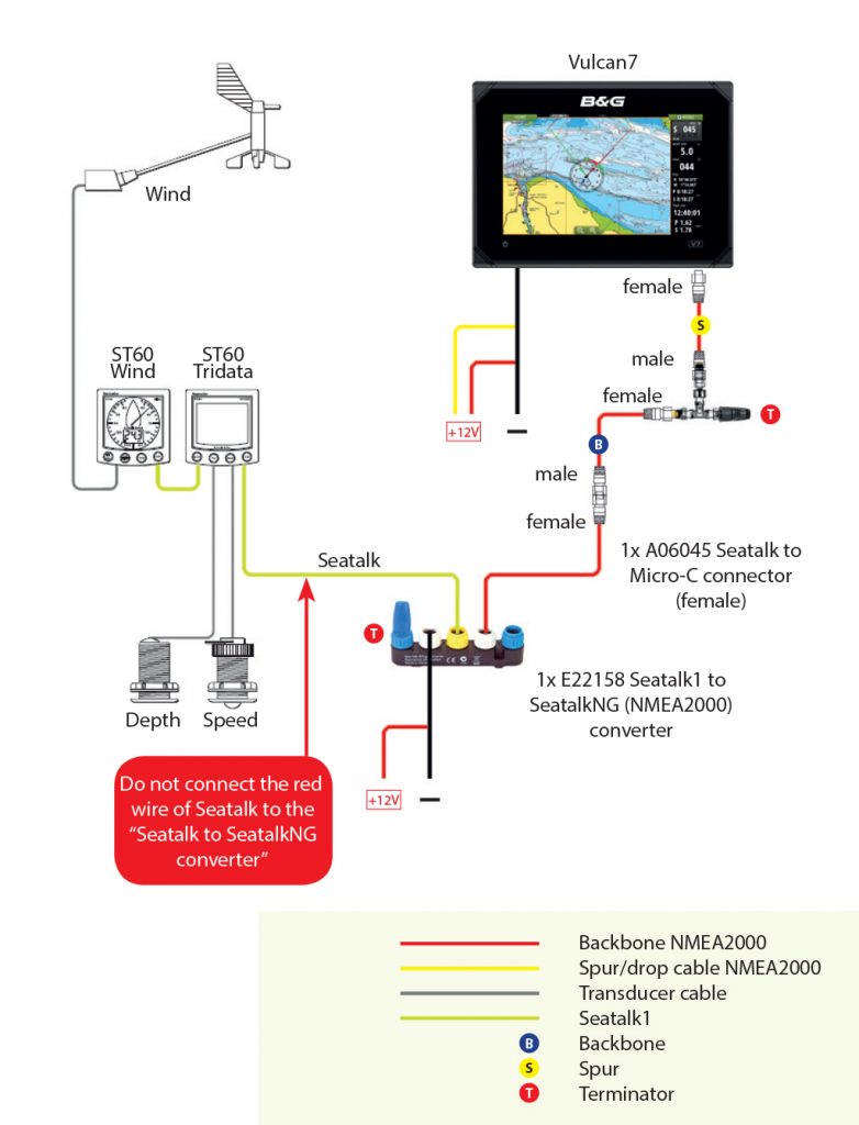
Installing Nmea 2000 Network Combined With Older Raymarine Seatalk Instruments Gear Anarchy Sailing Anarchy Forums
Https Encrypted Tbn0 Gstatic Com Images Q Tbn 3aand9gcsuwtwh0p3r0jv5pyd3 Ntutuhda1vawma4zqqocudwbduhwsti Usqp Cau
Connecting A Yamaha Engine Gateway To A Compatible Chartplotter Garmin Support

Es 0375 Nmea 2000 Wiring Schematic Wiring
Simnet Network Testing More Nse Goodies Panbo
Connecting Separately Powered Garmin And Suzuki Networks Page 2 The Hull Truth Boating And Fishing Forum
Installation Boatrax

Installing A Navlink2 Nmea 2000 To Wifi Server On A Seatalkng Network
Electronic Fuel Flow Sensor Sensor Lowrance Lowrance Usa
Garmin 7610 Wont Power Up Page 2 The Hull Truth Boating And Fishing Forum

Zm 2250 Raymarine Wiring Diagrams Free Diagram
Nmea 2000 Components The Gps Store Inc

Installing A Nmea 2000 To Wifi Server On A Garmin Nmea 2000 Network
Lowrance X135 Power Cable Wiring Diagram Lowrance Elite 7 Wiring Diagram Installing Evermore Sa 320 Smart Receiver To Lowrance 332c Lowrance Nmea 2000 Wiring Diagram Lowrance Power And Video Cable Wiring Diagram
03408 Marine Stereo User Manual 1 Garmin

Nmea 2000 Wiring Diagram Electrical Wires Cable Computer Network Nmea 0183 Atmospheric Card Computer Network Angle Png Pngegg
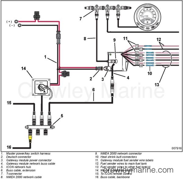
Evinrude Icon Gateway Module And Cable Kit P N 764922
Connecting Nmea 0183 Bare Wires Club Sea Ray

Remote Switching Of Nmea2000 Network
Nmea 0183 Nmea 2000 Wiring Diagram Electronics Electrical Cable Png Clipart Cable Harness Circuit Diagram Communication

Ancor 39 1 4 Nmea 2000 Power Cable With Tee West Marine

Lowrance Elite 7 Hdi Wiring Diagram Free Wiring Diagram In 2020 Circuit Drawing Wire Circuit Diagram

Nmea Interface Between Garmin 72 Lowrance Lcx17 The Hull Truth Boating And Fishing Forum
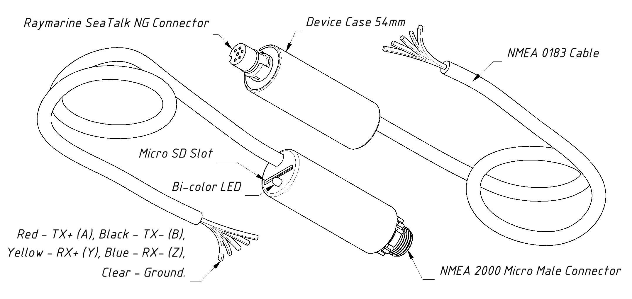
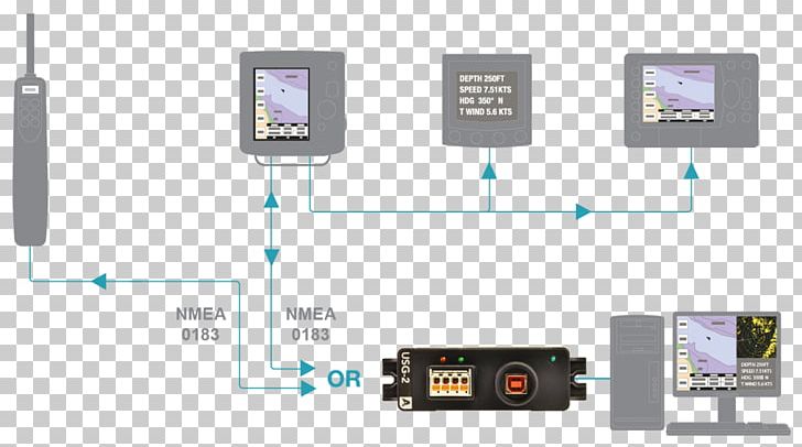
Nmea 0183 Gateway

Connecting Navlink2 To A Nmea 2000 Starter Kit From Digital Yacht